A robot is a complex machine made up of smaller simple machines that operate the robot.
Simple machines have existed and have been used for centuries. Each machine makes work easier to do by providing some trade-off between the force applied and the distance over which the force is applied.
A simple machine can make it easier to lift a load, with less force required; however, the Work remains the same. For example, if I need to raise a crate weighing 1 ton into the air I will use a pulley system to help me make it easier to lift. The weight of the crate is always the same but the (effort) force required to lift the weight is reduced.
SIMPLE MACHINES
There are six types of simple machines:
Wheel and Axle
Pulley
Lever
Inclined plane
Screw
Wedge
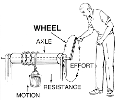
Wheel and Axle
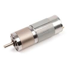
The wheel and axle uses a wheel with a rod attached in the middle as an axle to help it to lift or move loads. The BEST motor is an example of a wheel and axle.
Electricity is supplied to the motor that turns the shaft that in turn, turns the wheel.
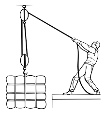
The Pulley
A pulley is a wheel and rope that can change the direction of a force. A flagpole uses a pulley to raise the flag. You can add several pulleys together and create a block and tackle that will reduce the amount of force needed to lift the load. The size of the load doesn’t change.
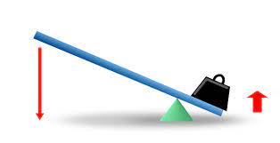
The lever
A lever is a bar or board that rests on a support called a fulcrum. A downward force exerted on one end of the lever can be transferred and increased in an upward direction at the other end, allowing a small force to lift a heavy weight.
There are three classes of levers, 1st class lever, 2nd class lever, and 3rd class lever
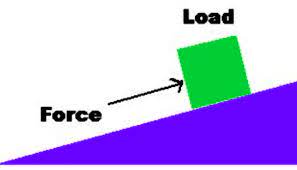
The inclined plane
An inclined plane consists of a sloping surface; it is used for raising heavy bodies. The plane offers a mechanical advantage in that the force required to move an object up the incline is less than the weight being raised
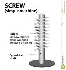
The Screw
A Screw is an inclined plane wrapped around a pole.
LEVERS
A lever is a stiff bar that rotates about a pivot point called the fulcrum. Depending on where the pivot point is located, a lever can multiply either the force applied or the distance over which the force is applied.
There are three classes of levers:
The arm on the robot moving up and down is an example of a lever
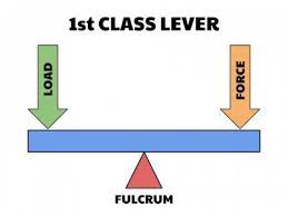
First Class Levers
The fulcrum is between the effort and the load. A seesaw is an example of a simple first class lever. A pair of scissors is an example of two connected first class levers.
1st Class Lever
Second Class Levers
The load is between the fulcrum and the effort. A wheelbarrow is an example of a simple second class lever. A nutcracker is an example of two connected second class levers.
2nd Class Lever
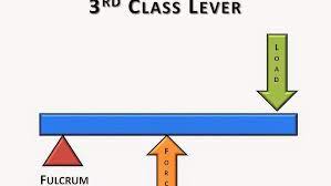
Third Class Levers
The effort is between the fulcrum and the load. A stapler or a fishing rod is an example of a simple third-class lever. A pair of tweezers is an example of two connected third-class levers.
3rd Class Lever
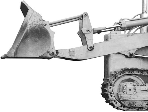
HOW MANY LEVERS CAN YOU FIND IN THE LOADER TO THE RIGHT?
THE LEVER BALANCE EQUATION FOR A FIRST CLASS LEVER IS :
W1D1-W2D2
THIS CAN BE DEMONSTRATED USING A RULER AS A LEVER AND COINS AS WEIGHTS
If more weights are to be added, simply add them to the required side of the equation. For example, to add an additional weight (W3), a distance (D3) to the right of the fulcrum makes the equation :
W1D1=W2D2+W3D3
PULLEYS / BLOCK AND TACKLE
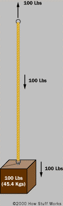
Imagine that you have the arrangement of a 100 pound weight suspended from a rope, as shown. If you are going to suspend the weight in the air then you have to apply an upward force of 100 pounds to the rope. If the rope is 100 feet long and you want to lift the weight up 100 feet, you have to pull in 100 feet of rope to do it.
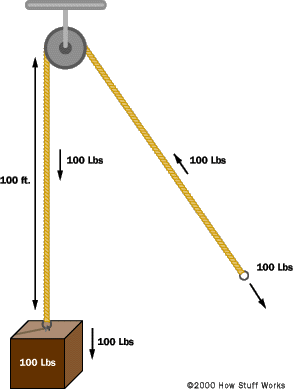
Now imagine that you add a pulley. Does this change anything? Not really. The only thing that changes is the direction of the force you have to apply to lift the weight. You still have to apply 100 pounds of force to keep the weight suspended, and you still have to reel in 100 feet of rope in order to lift the weight 100 feet.
BLOCK AND TACKLE
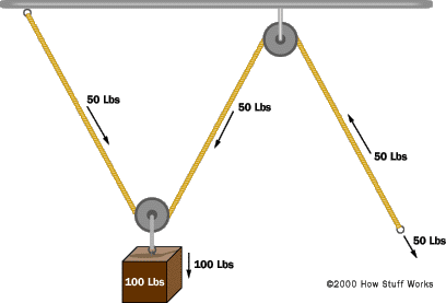
The following figure shows the arrangement after adding a second pulley.
This arrangement actually does change things in an important way. You can see that the weight is now suspended by two ropes rather than one. That means the weight is split equally between the two ropes, so each one holds only half the weight, or 50 pounds. That means that if you want to hold the weight suspended in the air, you only have to apply 50 pounds of force (the ceiling exerts the other 50 pounds of force on the other end of the rope). If you want to lift the weight 100 feet higher, then you have to reel in twice as much rope – 200 feet of rope must be pulled in. This demonstrates a force-distance tradeoff. The force has been cut in half but the distance the rope must be pulled has doubled.
GEARS
Gears are generally used for one of four different reasons:
To reverse the direction of rotation
To increase or decrease the speed of rotation
To move rotational motion to a different axis
To keep the rotation of two axis synchronized
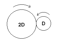
You can see effects 1, 2 and 3 in the figure
The two gears are rotating in opposite directions.
The smaller gear spins twice as fast as the larger gear because the diameter of the gear on the left is twice that of the gear on the right. The gear ratio is therefore 2:1 pronounced, “Two to one”).
The axis of rotation of the smaller gear is to the right of the axis of rotation for the larger gear.
If D is the motor and 2D is being driven, 2D has twice the torque. (Same effect can be accomplished with a belt).
The equation for torque is
T=rF
Where:
T = torque of the motor
r = radius of the motor shaft, pulley or whatever is attached to the motor shaft